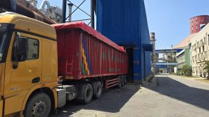
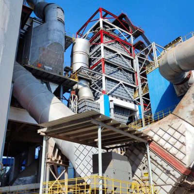
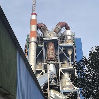
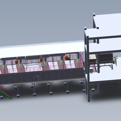
Exciting progress has been achieved at the Tieshan Cement Project of China Railway Materials in Maanshan: the alternative fuel silo equipment supplied by our company has completed one full month of stable continuous operation.
Background Challenge
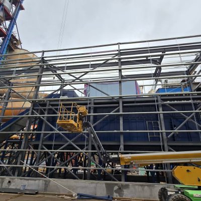
The available construction area on site is extremely limited. Conventional discharging, storage and feeding solutions fail to meet the high alternative fuel substitution ratio required by the cement kiln. Following our technical proposal, the project owner adopted our custom-engineered silo system tailored specifically for this project, successfully resolving the site constraint bottleneck.
Since commissioning, the equipment has demonstrated prominent advantages as listed below:
-
Compact & Rational Structural Design with Low O&M Costs
The equipment features a streamlined and well-conceived layout. Hydraulically driven stepwise discharging enables extremely user-friendly operation, allowing operators to handle complex material storage and conveying tasks with ease. Meanwhile, the equipment maintains minimal maintenance expenditure, greatly lowering long-term operational costs.
-
Intensive Automated Control for Safe & Stable Feeding
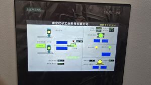
Deep integration of automatic control systems serves as a core highlight. The unit runs safely and steadily by starting and stopping the movable floor to precisely regulate discharge rate and output volume. It eliminates risks arising from manual misoperation and substantially enhances the safety and stability of the whole production line.
-
Excellent Environmental Performance with Dust Suppression
Equipped with dedicated unloading functions matched with a complete dust removal system, the facility effectively inhibits fugitive dust emission, creates a tidy and safe working environment, and fully complies with stringent modern environmental protection regulations.
-
Built-in Protection Interlocks & Multi-scenario Compatibility
The silo is equipped with material backfeeding protection, high material level prevention and overload feeding interlocks to avoid system overload caused by excessive feed volume. It supports integrated coordinated operation of the entire alternative fuel dosing system and is compatible with diverse feedstock including biomass pellets, wood chips, SRF and RDF to fit various production conditions.
Operational Benefits After One Month of Steady Operation
Compared with previous conventional equipment, the high-efficiency silo system drastically accelerates material circulation, streamlines production workflows and cuts idle waiting time in the process chain, delivering a marked improvement in overall production efficiency.
Follow-up Commitment
We will continue to monitor equipment operating conditions and conduct ongoing performance optimization to deliver robust long-term technical support for the sustainable development of the alternative fuel dosing project at China Railway Materials Tieshan Cement.
Furthermore, we aim to replicate this proven solution across more industrial projects to help elevate production efficiency and green manufacturing capabilities for partners across multiple industries.
SRF -moving floor system
Frequently Asked Technical Questions
Q1. Why choose a moving floor buffer bin instead of a conventional day silo for truck-delivered RDF?
Trucks deliver RDF in batches of 20-30 t at irregular intervals, while the kiln demands a steady 5-25 t/h. A buffer bin must therefore accept rapid tip-in (up to 300 t/h during a truck dump) and meter it out slowly. A conical steel silo with a screw discharger cannot do this for fibrous RDF: arching, ratholing and jamming of the screw are common, and silo volume above the cone is wasted because material does not flow. The moving floor buffer bin is a rectangular concrete or steel hall where a row of hydraulic pusher sections (typically 6-12 sections, each 1.2-2.0 m long) pushes the whole pile to a cross-conveyor. Saxlund’s Castle Cement tyre-chip bunker discharges at 1-7.2 t/h variable against a bulk density of 500-550 kg/m3, showing the wide turndown that pusher floors provide. Drive-over versions let two trucks tip simultaneously, cutting reception time to under 15 minutes per load.
Q2. What discharge rate and pusher spacing guarantee constant kiln feed from a buffer bin?
The discharge rate is set by the pusher stroke length, stroke frequency and floor width. A typical moving floor uses three groups of slats that move sequentially: group A advances 300-600 mm, the whole floor (A+B+C) returns, then B and C repeat. Each group is driven by double-acting hydraulic cylinders spaced on 1.0-1.5 m centers along the floor width, with the push plates themselves 100-150 mm thick hardened steel. At a stroke of 400 mm, a 5 m wide floor doing 2 strokes/min moves roughly 5 m x 0.4 m x 0.5 m (depth) x 2 strokes = 2 m3 per minute, or about 30 t/h at 0.25 t/m3. Variable-frequency hydraulic pumps turndown the rate 1:10, matching the upstream weighfeeder demand. The dp Energietechnik wood-chip installation uses six pusher sections feeding a scraper chain to the boiler, the same modular principle used for RDF buffers at cement plants.
Q3. How do you prevent self-heating and spontaneous combustion of RDF stored in a moving floor bin?
Stored RDF with moisture 15-25% and LHV 16-22 MJ/kg contains paper, plastics and residual organics that support aerobic microbial heating. The first line of defense is inventory control: design the bunker for 5-7 days of storage and enforce a first-in-first-out rotation so material does not dwell beyond 10-14 days. Second, install distributed fiber-optic or thermocouple temperature cables across the floor at 5 m spacing; alarms trigger at 55 degC and automatic extraction at 65 degC. Third, keep the hall under 30-60 Pa negative pressure with filtered recirculated air, which suppresses dust ignition and removes heat buildup. Fourth, segregate wood chips and RDF by material and moisture, because wet RDF (above 25%) heats faster than dry fluff. A fire water connection and high-expansion foam nozzle at the discharge end provide final backup, consistent with ATEX dust-group St1 requirements.
Q4. How does thyssenkrupp Polysius integrate the buffer bin with high-substitution combustion systems?
thyssenkrupp Polysius designs fuel substitution up to 100% thermal replacement using the polflame burner and prepol SC step combustor. The prepol SC burns waste on a grate with residence time above 1,000 seconds, versus only 7 seconds in a conventional calciner, which means it can accept coarsely shredded, higher-alkali RDF directly from the buffer bin without fine pulverization. The moving floor bin therefore feeds either (a) a PFISTER-style weighfeeder into the calciner for finely sized RDF (<30 mm), or (b) a separate metering conveyor to the prepol SC grate for coarser fractions. Chlorine and alkali inputs from the RDF stream are balanced by a 5% chlorine bypass that extracts kiln gas and condenses KCl/NaCl dust, keeping kiln-feed chlorine below 0.015% and preventing preheater ring formation. The buffer bin acts as the decoupling buffer between waste reception logistics and this demanding combustion window.
An expert in pyroprocess and solidwaste recovery . Responsible for the Marketing and Support of Sequoia Industrial with over 14 years in this field. I am determined that our sustainable products and services will be at the forefront of the solution for the generations to come.

 中文
 English





Comments (0)